Miele W 211 Operations Instructions
Browse online or download Operations Instructions for Cooker hoods Miele W 211. Miele W 211 Operating instructions User Manual
- Page / 44
- Table of contents
- BOOKMARKS
- Contents 3
- IMPORTANT SAFETY INSTRUCTIONS 4
- Guide to the appliance 8
- Functional description 10
- Operation 11
- Cleaning and Care 16
- After Sales Service 20
- Installation Instructions 21
- Caring for the environment 23
- Installation accessories 24
- Plywood backing 26
- Electrical data 27
- Appliance dimensions 28
- Installation 32
- Air extraction 42
- M.-Nr. 05 802 950 / 00 44
Summary of Contents
Operating and InstallationInstructionsVentilation SystemDA 211DA 217-3DA 218DA 219-3To prevent accidentsand machine damage,read these instructionsbefo
The hood offers two modes ofoperation:Air extractionThe air is drawn in and cleaned by thegrease filters and directed outside.The hood comes equipped
Turning on the fan^Press the On/Off button.The fan runs at power level "2".The On/Off indicator lights.Selecting the power level^Use the _ c
Delayed Shut DownIf odors or smoke remain in the kitchenafter cooking has been completed, theDelayed Shut Down feature can beselected to allow the hoo
Filter timersGrease filtersA timer monitors the hours of fanoperation. The indicator for the greasefilter will light after 30 hours ofoperation. The g
Reprogramming the timersThe grease filter timer is preset to 30hours. This time can be lengthened orshortened to 20, 30, 40 or 50 hours.–A time of 20
Reprogramming the charcoal filtertimerThe active charcoal filter can only beused in recirculation mode and can notbe used to exhaust fumes.The charcoa
Before cleaning or servicing thehood, disconnect it from the powersupply by either removing the fuse,unplugging it from the outlet ormanually "tr
Grease filtersThe reusable metal grease filtersremove solid particles from the ventedkitchen air (grease, dust, etc).The grease filters should be clea
Active charcoal filtersIn recirculation mode two activecharcoal filters must be used inaddition to the grease filters. Thecharcoal filters are designe
Changing the light bulbBefore changing the light bulbs,disconnect the hood from the powersupply by either removing the fuse,unplugging it, or manually
2
In the event of a fault which you can notcorrect yourself please contact:–Your Miele Dealeror–The Miele Technical ServiceDepartmentUSA 1-800-999-1360t
Installation Instructions
22
Disposal of packing materialThe cardboard box and packingmaterials protect the appliance duringshipping. They have been designed tobe biodegradable an
Installation accessories24
a 2 recirculation vents(recirculation mode only)b 2 protective shieldsprevent scratches to the chimneyduring installation.c 1 protective shieldprevent
The majority of the weight of theinstalled ventilation system will besupported by retaining plate A. Itmust be firmly attached to the studframing behi
All electrical work should beperformed by a qualified electricianin strict accordance with nationaland local safety regulations.Installation, repairs
Appliance dimensions28
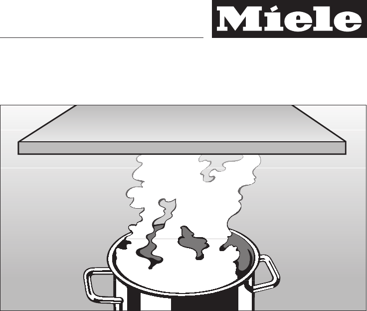
Do not install this exhaust hood overcooktops burning solid fuel.When installing the hood, make surethat the following minimumdistance (S) between the
IMPORTANT SAFETY INSTRUCTIONSGuide to the applianceFunctional descriptionOperationTurning on the fan . . . . . . . . . . . . . . . . . . . . . . . . .
If the standard unit height H is not suitable to the kitchen’s ceiling height, longeroptional chimney extensions are available from your Miele dealer
DA 218 Extraction RecirculationStandard unit H 281/8" - 375/8"715 mm - 955 mm3111/16" - 4015/16"805 mm - 1040 mmDATK 217/219 605 3
Retaining platesThe ventilation system will be mountedto the wall through the use of retainingplates. Plate A is installed first,followed by plate B.
Retaining plate A^Drill two1/8" (3 mm) holes, one at S +4" (100 mm) and one at S + 163/4"(425 mm) on the center line for theretaining p
Retaining plate CRetaining plate C should only be used ifdimension Y is greater than 143/8"(365 mm.) It provides additionalstability for the chim
Inserting the non-return flap^Air extraction:If a non-return flap is not present inthe venting system, the non-returnflap supplied must be fitted into
Electrical connectionBefore connecting the applianceread the "Warning and SafetyInstructions" and the "Electrical data"sections.^
Recirculation connectionRecirculation mode is used whenventing to the outside of the building isnot possible.^Slide the diverter on to the bracketsof
Attaching the chimneyextensionThe use of a chimney extension, allowsthe hood to be installed at variousdistances from the ceiling.NOTE: The extension
^Remove the protective foil fromchimney extension.^ Bend the top hanging tabs 45°inwards. This will make installing theextension easier. Be careful of
Read these Operating Instructions carefully before installing orusing the Ventilation System.This appliance is intended forresidential use only. Use t
Attaching the chimney^Fold the protective shield at the top.^ Remove the adhesive backing fromthe shield.^ Stick the shield to the chimneyextension so
^ Pull the chimney apart slightlyandslide it over the chimney extension.Do this carefully to prevent scatchingthe two pieces.^ Slide the chimney down
,WARNINGDanger of toxic fumes.Gas cooking appliances releasecarbon monoxide that can beharmful or fatal if inhaled.The exhaust gases extracted bythe h
– If the exhaust is ducted into aninactive flue, the air must be expelledparallel to the flow direction of theflue.Never connect an exhaust hood toan
M.-Nr. 05 802 950 / 00Alteration rights reserved / 1703This bio-friendly paper was bleached without the use of chlorine.
This equipment is not designed formaritime use or for use in mobileinstallations such as caravans oraircraft. However, under certainconditions it may
, WARNING - TO REDUCETHE RISK OF A RANGE TOPGREASE FIRE:Never leave surface unitsunattended at high settings.Boilovers cause smoking and greasyspillov
Installation, WARNINGTo reduce the risk of fire onlyuse metal ductwork.When installing the hood, follow therecommended minimum safetydistances between
Guide to the appliance8
a Chimney extensionb Chimneyc Canopyd Control panele Active charcoal filterf Recirculation ventg Overhead lightingh Grease filtersi Light buttonj On/O
Related products and manuals for Cooker hoods Miele W 211
 (40 pages)
(40 pages)
(40 pages)
(40 pages)
(40 pages)


 (56 pages)
© 2020, manymanuals.com. All rights reserved. | 4.473 s |
 Manymanuals.com
 Manymanuals.de
 Manymanuals.fr
 Manymanuals.it
 Manymanuals.pl
 Manymanuals.cz
 Manymanuals.es
 Manymanuals-pt.com
Comments to this Manuals